| SKU |
109706 Model Kodu: BZMD1-A16 |
|
| descriptionLabel |
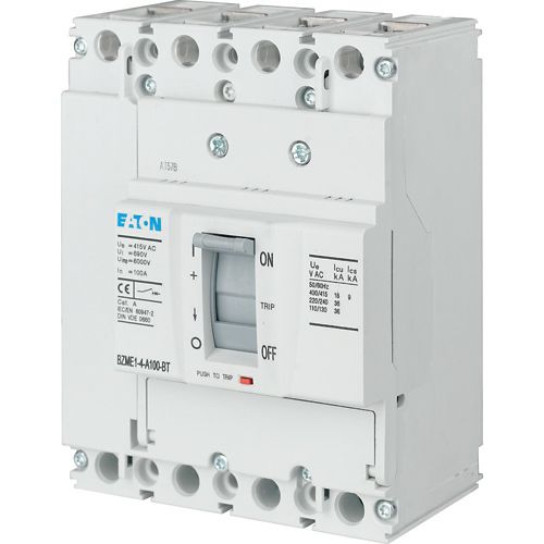
Eaton Moeller series Circuit breaker BZMD1, Three-pole, 16 A, 415 V, Screw connection |
|
| General specifications |
|
|
| |
Product Name |
Eaton Moeller series BZM - Molded case circuit breaker |
| |
Catalog Number |
109706 |
| |
EAN |
4015081092925 |
| |
Product Length/Depth |
130.2 mm |
| |
Product Height |
86 mm |
| |
Product Width |
75 mm |
| |
Product Weight |
0.83 kg |
| |
Compliances |
RoHS conform |
| |
Model Code |
BZMD1-A16 |
| Delivery program |
|
|
| |
Type |
Circuit breaker |
| |
Number of poles |
Three-pole |
| |
Amperage Rating |
16 A |
| |
Features |
Protection unit |
| Technical Data - Electrical |
|
|
| |
Voltage rating |
415 V - 415 V |
| |
Amperage Rating |
16 A |
| |
Instantaneous current setting (Ii) - min |
256 A |
| |
Instantaneous current setting (Ii) - max |
384 A |
| |
Overload current setting (Ir) - min |
0 A |
| |
Overload current setting (Ir) - max |
0 A |
| |
Short delay current setting (Isd) - min |
0 A |
| |
Short delay current setting (Isd) - max |
0 A |
| |
Rated short-circuit breaking capacity Ics (IEC/EN 60947) at 400/415 V, 50/60 Hz |
15 kA |
| |
Electrical connection type of main circuit |
Screw connection |
| |
Handle type |
Rocker lever |
| |
Overvoltage category |
III |
| |
Pollution degree |
3 |
| Technical Data - Mechanical |
|
|
| |
Mounting Method |
DIN rail (top hat rail) mounting optional Built-in device fixed built-in technique |
| |
Mounting Method |
DIN rail (top hat rail) mounting optional Built-in device fixed built-in technique |
| |
Degree of protection |
IP20 |
| |
Number of auxiliary contacts (change-over contacts) |
0 |
| |
Number of auxiliary contacts (normally closed contacts) |
0 |
| |
Number of auxiliary contacts (normally open contacts) |
0 |
| |
Position of connection for main current circuit |
Front side |
| Design verification as per IEC/EN 61439 - technical data |
|
|
| |
Rated operational current for specified heat dissipation (In) |
16 A |
| |
Equipment heat dissipation, current-dependent |
3.4 W |
| Design verification as per IEC/EN 61439 |
|
|
| |
10.2.2 Corrosion resistance |
Meets the product standard's requirements. |
| |
10.2.3.1 Verification of thermal stability of enclosures |
Meets the product standard's requirements. |
| |
10.2.3.2 Verification of resistance of insulating materials to normal heat |
Meets the product standard's requirements. |
| |
10.2.3.3 Resist. of insul. mat. to abnormal heat/fire by internal elect. effects |
Meets the product standard's requirements. |
| |
10.2.4 Resistance to ultra-violet (UV) radiation |
Meets the product standard's requirements. |
| |
10.2.5 Lifting |
Does not apply, since the entire switchgear needs to be evaluated. |
| |
10.2.6 Mechanical impact |
Does not apply, since the entire switchgear needs to be evaluated. |
| |
10.2.7 Inscriptions |
Meets the product standard's requirements. |
| |
10.3 Degree of protection of assemblies |
Does not apply, since the entire switchgear needs to be evaluated. |
| |
10.4 Clearances and creepage distances |
Meets the product standard's requirements. |
| |
10.5 Protection against electric shock |
Does not apply, since the entire switchgear needs to be evaluated. |
| |
10.6 Incorporation of switching devices and components |
Does not apply, since the entire switchgear needs to be evaluated. |
| |
10.7 Internal electrical circuits and connections |
Is the panel builder's responsibility. |
| |
10.8 Connections for external conductors |
Is the panel builder's responsibility. |
| |
10.9.2 Power-frequency electric strength |
Is the panel builder's responsibility. |
| |
10.9.3 Impulse withstand voltage |
Is the panel builder's responsibility. |
| |
10.9.4 Testing of enclosures made of insulating material |
Is the panel builder's responsibility. |
| |
10.10 Temperature rise |
The panel builder is responsible for the temperature rise calculation. Eaton will provide heat dissipation data for the devices. |
| |
10.11 Short-circuit rating |
Is the panel builder's responsibility. The specifications for the switchgear must be observed. |
| |
10.12 Electromagnetic compatibility |
Is the panel builder's responsibility. The specifications for the switchgear must be observed. |
| |
10.13 Mechanical function |
The device meets the requirements, provided the information in the instruction leaflet (IL) is observed. |

 TR
TR ENG
ENG

Yorumlar