| SKU |
266021 Model Kodu: PN3-4-400 |
|
| descriptionLabel |
Eaton Moeller series NZM - Molded Case Circuit Breaker. Switch-disconnector 4p, 400A, 3 |
|
| General specifications |
|
|
| |
Product Name |
Eaton Moeller series NZM switch-disconnector |
| |
Catalog Number |
266021 |
| |
EAN |
4015082660215 |
| |
Product Length/Depth |
159 mm |
| |
Product Height |
275 mm |
| |
Product Width |
185 mm |
| |
Product Weight |
6.22 kg |
| |
Compliances |
RoHS conform |
| |
Certifications |
IEC/EN 60947 IEC |
| |
Model Code |
PN3-4-400 |
| Delivery program |
|
|
| |
Application |
Use in unearthed supply systems at 690 V |
| |
Type |
Switch-disconnector |
| |
Circuit breaker frame type |
PN4 |
| |
Number of poles |
Four-pole |
| |
Amperage Rating |
400 A |
| |
Features |
Version as maintenance-/service switch Version as emergency stop installation Version as main switch |
| |
Special features |
Main switch characteristics including positive drive to IEC/EN 60204 and VDE 0113.Isolating characteristics to IEC/EN 60947-3 and VDE 0660.Busbar tag shroud to VDE 0160 Part 100.Rated current = rated uninterrupted current: 400 A |
| Technical Data - Electrical |
|
|
| |
Voltage rating |
690 V - 690 V |
| |
Rated operating voltage (Ue) at AC - max |
690 V |
| |
Rated insulation voltage (Ui) |
1000 V |
| |
Rated impulse withstand voltage (Uimp) at auxiliary contacts |
6000 V |
| |
Rated impulse withstand voltage (Uimp) at main contacts |
8000 V |
| |
Rated operational current |
630 A (690 V AC-22/23A, making and breaking capacity) 630 A (415 V AC-22/23A, making and breaking capacity) |
| |
Rated conditional short-circuit current with back-up fuse |
100 kA at 400/415 V PN3(N3)-400…630: 630 AgGgL 80 kA at 690 V |
| |
Rated conditional short-circuit current with downstream fuse |
80 kA at 690 V 100 kA at 400/415 V PN3(N3)-400…630: 630 AgGgL |
| |
Rated short-time withstand current (t = 0.3 s) |
12 kA |
| |
Rated short-time withstand current (t = 1 s) |
12 kA |
| |
Amperage Rating |
400 A |
| |
Rated operating frequency |
50 Hz |
| |
Rated short-circuit making capacity Icm at 690 V, 50/60 Hz |
25 kA |
| |
Rated operating power at AC-23, 400 V |
200 kW |
| |
Short-circuit protective device fuses - max |
630 A gL |
| |
Electrical connection type of main circuit |
Screw connection |
| |
Isolation |
500 V AC (between auxiliary contacts and main contacts) 300 V AC (between the auxiliary contacts) |
| |
Number of operations per hour - max |
60 |
| |
Handle type |
Rocker lever |
| |
Overvoltage category |
III |
| |
Pollution degree |
3 |
| |
Lifespan, electrical |
3000 operations at 400 V AC-3 3000 operations at 690 V AC-1 5000 operations at 415 V AC-1 5000 operations at 400 V AC-1 3000 operations at 415 V AC-3 2000 operations at 690 V AC-3 |
| |
Direction of incoming supply |
As required |
| Technical Data - Mechanical |
|
|
| |
Mounting Method |
Intermediate mounting Built-in device fixed built-in technique Ground mounting Fixed Distribution board installation |
| |
Mounting Method |
Intermediate mounting Built-in device fixed built-in technique Ground mounting Fixed Distribution board installation |
| |
Degree of protection |
IP20 (basic protection type, in the area of the HMI devices) Other |
| |
Degree of protection (IP), front side |
IP66 (with door coupling rotary handle) IP40 (with insulating surround) IP20 |
| |
Degree of protection (terminations) |
IP00 (terminations, phase isolator and band terminal) IP10 (tunnel terminal) |
| |
Protection against direct contact |
Finger and back-of-hand proof to DIN EN 50274/VDE 0106 part 110 |
| |
Shock resistance |
20 g (half-sinusoidal shock 20 ms) |
| |
Number of auxiliary contacts (change-over contacts) |
0 |
| |
Number of auxiliary contacts (normally closed contacts) |
0 |
| |
Number of auxiliary contacts (normally open contacts) |
0 |
| |
Number of switches |
1 |
| |
Handle color |
Black |
| |
Switch positions |
I, 0 |
| |
Climatic proofing |
Damp heat, constant, to IEC 60068-2-78 Damp heat, cyclic, to IEC 60068-2-30 |
| |
Special features |
Main switch characteristics including positive drive to IEC/EN 60204 and VDE 0113.Isolating characteristics to IEC/EN 60947-3 and VDE 0660.Busbar tag shroud to VDE 0160 Part 100.Rated current = rated uninterrupted current: 400 A |
| |
Lifespan, mechanical |
15000 operations |
| Technical Data - Mechanical - Terminals |
|
|
| |
Standard terminals |
Screw terminal |
| |
Optional terminals |
Box terminal. Connection on rear. Tunnel terminal |
| |
Terminal capacity (aluminum solid conductor/cable) |
16 mm² (1x) at tunnel terminal 16 mm² (1x) direct at switch rear-side connection 10 mm² - 16 mm² (2x) direct at switch rear-side connection |
| |
Terminal capacity (aluminum stranded conductor/cable) |
25 mm² - 185 mm² (1x) at 1-hole tunnel terminal up to 240 mm² depending on the cable manufacturer. |
| |
Terminal capacity (copper busbar) |
Min. 20 mm x 5 mm direct at switch rear-side connection Max. 10 mm x 50 mm (2x) at rear-side width extension Max. 30 mm x 10 mm + 30 mm x 5 mm direct at switch rear-side connection M10 at rear-side screw connection |
| |
Terminal capacity (copper solid conductor/cable) |
16 mm² (2x) at box terminal 16 mm² (1x) direct at switch rear-side connection 300 mm² (2x) at rear-side width extension 16 mm² (2x) direct at switch rear-side connection |
| |
Terminal capacity (copper stranded conductor/cable) |
25 mm² - 120 mm² (2x) at box terminal 25 mm² - 120 mm² (1x) direct at switch rear-side connection 50 mm² - 240 mm² (1x) at 2-hole tunnel terminal 25 mm² - 120 mm² (2x) direct at switch rear-side connection 35 mm² - 240 mm² (1x) at box terminal 25 mm² - 185 mm² (1x) at 1-hole tunnel terminal 50 mm² - 240 mm² (2x) at 2-hole tunnel terminal |
| |
Terminal capacity (copper strip) |
Min. 6 segments of 16 mm x 0.8 mm at rear-side connection (punched) Max. 8 segments of 24 mm x 1 mm (2x) at box terminal 10 segments of 50 mm x 1 mm (2x) at rear-side width extension Max. 10 segments of 24 mm x 1 mm + 5 segments of 24 mm x 1 mm Max. 10 segments of 32 mm x 1 mm + 5 segments of 32 mm x 1 mm at rear-side connection (punched) Min. 6 segments of 16 mm x 0.8 mm at box terminal |
| Design verification as per IEC/EN 61439 - technical data |
|
|
| |
Rated operational current for specified heat dissipation (In) |
400 A |
| |
Equipment heat dissipation, current-dependent |
43.2 W |
| |
Ambient operating temperature - min |
-25 °C |
| |
Ambient operating temperature - max |
70 °C |
| |
Ambient storage temperature - min |
-40 °C |
| |
Ambient storage temperature - max |
70 °C |
| Design verification as per IEC/EN 61439 |
|
|
| |
10.2.2 Corrosion resistance |
Meets the product standard's requirements. |
| |
10.2.3.1 Verification of thermal stability of enclosures |
Meets the product standard's requirements. |
| |
10.2.3.2 Verification of resistance of insulating materials to normal heat |
Meets the product standard's requirements. |
| |
10.2.3.3 Resist. of insul. mat. to abnormal heat/fire by internal elect. effects |
Meets the product standard's requirements. |
| |
10.2.4 Resistance to ultra-violet (UV) radiation |
Meets the product standard's requirements. |
| |
10.2.5 Lifting |
Does not apply, since the entire switchgear needs to be evaluated. |
| |
10.2.6 Mechanical impact |
Does not apply, since the entire switchgear needs to be evaluated. |
| |
10.2.7 Inscriptions |
Meets the product standard's requirements. |
| |
10.3 Degree of protection of assemblies |
Does not apply, since the entire switchgear needs to be evaluated. |
| |
10.4 Clearances and creepage distances |
Meets the product standard's requirements. |
| |
10.5 Protection against electric shock |
Does not apply, since the entire switchgear needs to be evaluated. |
| |
10.6 Incorporation of switching devices and components |
Does not apply, since the entire switchgear needs to be evaluated. |
| |
10.7 Internal electrical circuits and connections |
Is the panel builder's responsibility. |
| |
10.8 Connections for external conductors |
Is the panel builder's responsibility. |
| |
10.9.2 Power-frequency electric strength |
Is the panel builder's responsibility. |
| |
10.9.3 Impulse withstand voltage |
Is the panel builder's responsibility. |
| |
10.9.4 Testing of enclosures made of insulating material |
Is the panel builder's responsibility. |
| |
10.10 Temperature rise |
The panel builder is responsible for the temperature rise calculation. Eaton will provide heat dissipation data for the devices. |
| |
10.11 Short-circuit rating |
Is the panel builder's responsibility. The specifications for the switchgear must be observed. |
| |
10.12 Electromagnetic compatibility |
Is the panel builder's responsibility. The specifications for the switchgear must be observed. |
| |
10.13 Mechanical function |
The device meets the requirements, provided the information in the instruction leaflet (IL) is observed. |
| Additional information |
|
|
| |
Functions |
Disconnectors/main switches Interlockable |
 TR
TR ENG
ENG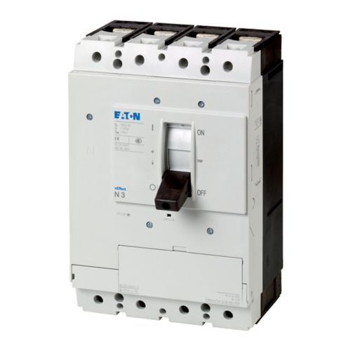

Yorumlar